Raspberry PI garage door opener - Part 1
I’ve been meaning to write up this post for a year or so, but it’s gotten away from me. This is about a project I created to replace a physical garage door opener, with technology. I’m an avid self-hoster and automation nerd; raspberry-pi’s fit into a lot of projects I do. So I set out to use one as a garage door opener with more control. Sort of self-hosted, do-it-yourself, remotely accessible garage door opener project! This isn’t entirely self-hosted, only about 95% so. But it was definitely a learning experience, a lot of fun, and practical!
I’m not going to explain how to setup the Raspberry PI with an OS or what a GPIO pin is. This is a brain dump on what I did to achieve my project goals.
Project purpose
I was tired of replacing the batteries in our garage door openers and wanted to find a better solution. My goals were to be able to open the garage doors from my phone easily and without third-party subscription based service. Of course I thought about using a raspberry-pi to control the garage doors I have, while being remotely accessible. This led me down a lot of rabbit holes and different levels of connectivity or solutions. You can find a lot of projects through your favorite search engine, but I didn’t want a pre-made solution or one that was tied to a 3rd party vendor at a yearly subscription cost. Although I did review a few of those for ideas and pitfalls, I still wanted to create my own and ideally as fully self-hosted as possible. Because part of the goals of the project were to be remotely accessible and via SMS, I couldn’t rely on a 100% self hosted solution.
The plan to achieve it was thus: Setup and configure a raspberry pi with a base/lite OS. Hook up GPIO pins to a relay to control signal to the garage door opener buttons. Attach a sensor to the garage door to determine if its open or closed, reporting to the r-pi. Ensure the r-pi opener works locally and then configure remote SMS control. The remote SMS based control was crucial to actually have a usable system. This enables the family to open or close the garage door from their phone as needed, instead of finding out the opener battery is dead. Again.
Components
These are the parts I used after researching and planning:
Hardware
- 1 Raspberry PI Zero W
- 2 Seco-Larm SM-226L-Q
- 1 sainsmart two channel DC 5V Relay Module
- 1 pkg female to female jumper wires
- 100 ft 20⁄2 residential bell wire
- 2 existing Chamberlin garage door openers
- wire nuts and electrical tape
Software
- Custom golang processing program
- SMS gateway - SignalWire
- PHP script for web page
- Nginx web server
The garage doors themselves, openers and interior garage buttons were already there; didn’t need to buy anything for that! Just a matter of wiring up the PI and relay to the interior buttons.
Setting up the hardware
First things first I had to make sure all the hardware works and install the sensors/wires for them. I chose to install the Seco-Larm SM-226LQ sensors which are closed loop magnetic proximity sensors. Closed loop just means it can signal state without any human intervention or manual input. This is the two wire model, the ground wire and the ‘signaling’ wire that will report the status of the sensor. When the circuit is closed, the sensors are close together. Circuit open/broken and the sensors are farther apart. This translate to the garage door being open (further apart) or closed (closed ciruit).
The sensor came with a metal L bracket that I screwed into the top of the garage door to afix the magnet.
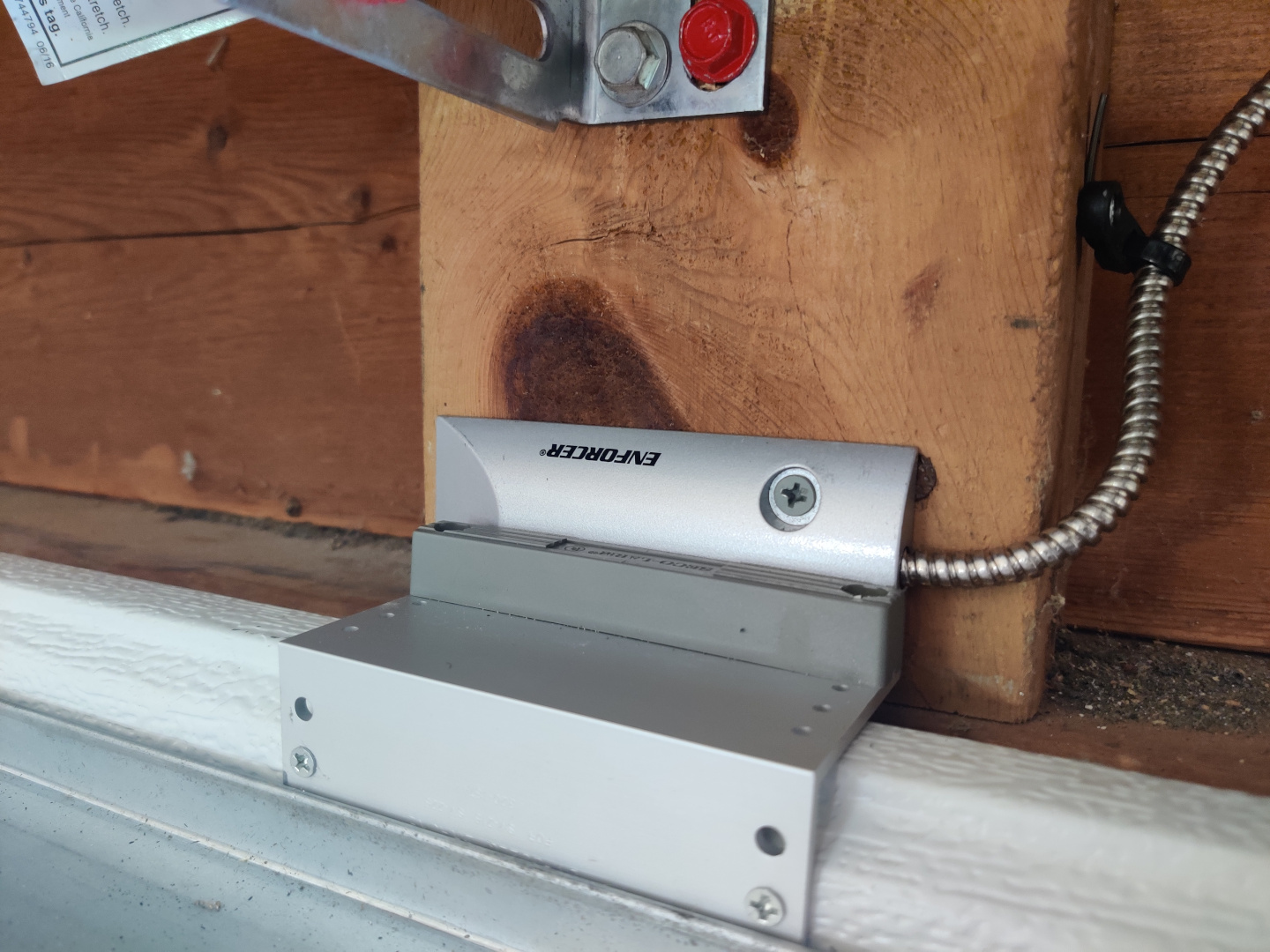

The contacts are real close in this picture but you don’t need them so close or even touching. The Seco-Larm can register the circuit change at about two inches apart! After placing the sensors it was just a matter of attaching the wires to the proper places. For the wires coming out of the Seco-Larm, black is the ground, green wire is the one that goes low if the circuit is closed and goes high if it is open. Basically, voltage on or off. I used the 20⁄2 bell wiring to extend the sensor wires to where they needed to be, ending at the location of where the R-PI will be stationed. Then spliced the wire from the sensors into a f-to-f jumper wire so at the next step I could attach them to the GPIO pins on the pi. Next step was to attach some more bell wire to the interior garage door opener buttons and run them to the 2-channel relay. The relay is what’s actually responsible for triggering the garage door opener after it gets the signal from the pi. One relay goes to the door opener on the left and one goes to the right.
The garage door opener mounted in the garage is easy to remove. On the back not shown are two screws with the existing wires wrapped around them. The new wires just need to be wrapped around the screws and then tightened down. Essentially pigging backing the wires in the same space as the existing wires. In my testing it didn’t matter which one was the red or white wire so I didn’t bother to voltage test. When triggered, as long as the circuit was complete, it works.

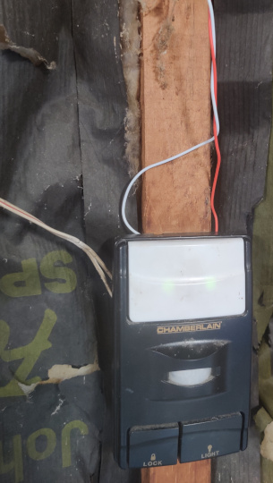
In this manner, you can still push the interior button to trigger the garage door to open or close while the pi and relay can do the same when told to! The wires in the above image going UP are to the relay, the ones to the left are to the garage door opener itself. Final steps for ths part are to attach the wires from the sensors and relay to the R-PI GPIO pins in the proper locations.

For each of the wires you have to splice them into a female jumper in order to get them attached securely to the RPI. The relay itself needs 5v power from the PI. I used physical pin 2 connected to the power jumper on the relay for this. Next the wires to actual trigger the relay, one for each relay to the board. I used physical pin 7 (GPIO 4) and the ground next to it for one and physical pin 40 (GPIO 21) for the other. I wanted them to be as far apart as possible to prevent crosstalk triggering inadvertently. Then I connected the sensor wires, phyiscal pin 13 and the ground next to it and physical pin 33 and the ground next to it. When referencing the pins from the software it uses the GPIO numbers and not the physical pin numbers. The above image is what I used to cross reference those numbers.
Connecting the wires from the Raspberry Pi to the relay is straightforward as well. Making sure to note wich RPI GPIO is for which ‘side’, connect the other end of the wire into the relay jumper for that door. On the module those signaling jumpers are labeled IN1, and IN2. Then run a wire from the GND on the relay to a Ground pin on the pi and connect the VCC pin to a 5V power pin; I used pin 2 on PI. That’s it! The pi should send power to the relay and signal it properly when the GPIO triggers.
Next time on …
That’s it for the hardware side of things. In the next post I’ll go over the software creation and process of connecting all the pieces together.

Proudly written with VIM, pushed to gitea and processed with golang static site generator